Saturday, 6 February 2021

Analog Modulation & It’s types


Analog modulation is further divided into three types:

 Amplitude modulation.
 Frequency modulation.
 Phase modulation.

Amplitude Modulation:

Amplitude modulation is a process by which the wave signal is transmitted by modulating the amplitude of the signal. Amplitude modulation or AM as it is often called, is a form of modulation used for radio transmissions for broadcasting and two-way radio communication applications. Although one of the earliest used forms of modulation it is still used today, mainly for long, medium, and short-wave broadcasting and for some aeronautical point to point communications. Currently, this technique is used in many areas of communication such as in portable two-way radios, citizens band radio, VHF aircraft radio and in modems for computers. Amplitude modulation is also used to mention the mediumwave AM radio broadcasting.
One of the key reasons for the use of amplitude modulation was its ease of use. The system simply required the carrier amplitude to be modulated, but more usefully the detector required in the receiver could be a simple diode-based circuit. This meant that AM radios did not need complicated demodulators and costs were reduced - a key requirement for widespread use of radio technology, especially in the early days of radio when ICs were not available.
 
In general, amplitude modulation definition is given as a type of modulation where the amplitude of the carrier wave is varied in some proportion with respect to the modulating data or the signal.

Types of Amplitude Modulation:

o Double sideband-suppressed carrier modulation (DSB-SC).
o Single Sideband Modulation (SSB).
o Vestigial Sideband Modulation (VSB).

Advantages of Amplitude Modulation:

• Easier to implement.
• Simple demodulation circuit.
• Cheap receiver.

Disadvantages of Amplitude Modulation:

• AM signal is not efficient in terms of power usages.
• Use of bandwidth not efficient.
• Noise interference is high.

Thursday, 28 November 2019

What is Modulation?

Modulation is a process through which audio, video, image or text information is added to an electrical or optical carrier signal to be transmitted over a telecommunication or electronic medium. 

Modulation is the process of varying one or more properties of a periodic waveform, called the carrier signal, with a modulating signal that typically contains information to be transmitted. Most radio systems in the 20th century used frequency modulation (FM) or amplitude modulation (AM) for radio broadcast. 

Modulation enables the transfer of information on an electrical signal to a receiving device that demodulates the signal to extract the blended information.

Need for Modulation:

Baseband signals are incompatible for direct transmission. For such a signal, to travel longer distances, its strength must be increased by modulating with a high frequency carrier wave, which doesn’t affect the parameters of the modulating signal.

Modulator used for modulation and demodulator used for demodulating signals in its original form. A modem is a common example of a modulation technique in which the data is modulated with electrical signals and transmitted over telephone lines. It is later demodulated to receive the data.

There are basically two methods of modulations:

1.Analog Modulations Method
2.Digital Modulations Method

Friday, 11 January 2019

What is RF?


Radio frequency (RF) refers to the rate of oscillation of electromagnetic radio waves in the range of up to 300 GHz lower range exactly we can't define but we measured it from 9KHz, as well as the alternating currents carrying the radio signals. This is the frequency band that is used for communications transmission and broadcasting. Although RF really stands for the rate of oscillation of the waves, it is synonymous to the term "radio," or simply wireless communication.

 Radio frequency is being used in a lot of fields, but in the context of information and communications technology it refers to the frequency band at which wireless telecommunications signals are being transmitted and broadcast. The frequency band is being divided into different parts, which are then assigned to different technology industries. This is known as the radio spectrum. For example, the VHF (very high frequency) band, which ranges from 30-300 MHz, is being used for FM radio, TV broadcasts, and amateur radio and its counterparts. For a lot of electronic communication devices, the ultra-high frequency (UHF) band is being used. This is the space used by mobile phones, wireless LAN, Bluetooth, and TV and land radio.

Radio frequency is produced by oscillating current a specified number of times and then radiating it off a conductor, referred to as an antenna, into empty space (this refers to space occupied by air rather than solid objects and does not refer to outer space) as electromagnetic radio waves. RF signals are sent and received using conductors through the phenomenon known as the skin effect, where RF current latches itself and flows through the surface of conductors rather than penetrating and passing through them like it does with other non-conducting solids. This effect is the core and basis of radio technology.

Monday, 20 November 2017

What is anAntenna


An Antenna is a transducer, which converts electrical power into electromagnetic waves
and vice versa.
An Antenna can be used either as a transmitting antenna or a receiving antenna.
 A transmitting antenna is one, which converts electrical signals into
electromagnetic waves and radiates them.
 A receiving antenna is one, which converts electromagnetic waves from the
received beam into electrical signals.
 In two-way communication, the same antenna can be used for both transmission
and reception.
Antenna can also be termed as an Aerial. Plural of it is, antennae or antennas. Now-a-
days, antennas have undergone many changes, in accordance with their size and shape.
There are many types of antennas depending upon their wide variety of applications.

Saturday, 28 January 2017

Transistor

A transistor is a semiconductor device used to amplify or switch electronic signals and electrical power. It is composed of semiconductor material usually with at least three terminals for connection to an external circuit. A voltage or current applied to one pair of the transistor’s terminals controls the current through another pair of terminals. Because the controlled (output) power can be higher than the controlling (input) power, a transistor can amplify a signal.

How it works

A transistor is really simple and really complex. Let’s start with the simple part. A transistor is a miniature electronic component that can do two different jobs. It can work either as an amplifier or a switch:


  • When it works as an amplifier, it takes in a tiny electric current at one end (an input current) and produces a much bigger electric current (an output current) at the other. In other words, it's a kind of current booster. That comes in really useful in things like hearing aids, one of the first things people used transistors for. A hearing aid has a tiny microphone in it that picks up sounds from the world around you and turns them into fluctuating electric currents. These are fed into a transistor that boosts them and powers a tiny loudspeaker, so you hear a much louder version of the sounds around you. William Shockley, one of the inventors of the transistor, once explained transistor-amplifiers to a student in a more humorous way: "If you take a bale of hay and tie it to the tail of a mule and then strike a match and set the bale of hay on fire, and if you then compare the energy expended shortly thereafter by the mule with the energy expended by yourself in the striking of the match, you will understand the concept of amplification."
  • Transistors can also work as switches. A tiny electric current flowing through one part of a transistor can make a much bigger current flow through another part of it. In other words, the small current switches on the larger one. This is essentially how all computer chips work. For example, a memory chip contains hundreds of millions or even billions of transistors, each of which can be switched on or off individually. Since each transistor can be in two distinct states, it can store two different numbers, zero and one. With billions of transistors, a chip can store billions of zeros and ones, and almost as many ordinary numbers and letters (or characters, as we call them). More about this in a moment.

Wednesday, 5 March 2014

PLC (Programmable Logic Controller)

A programmable logic controller is a digital computer used for automation of electromechanical processes, such as control of machinery on factory assembly lines, amusement rides, or light fixtures. PLCs are used in many industries and machines. Unlike general-purpose computers, the PLC is designed for multiple inputs and output arrangements, extended temperature ranges, immunity to electrical noise, and resistance to vibration and impact. Programs to control machine operation are typically stored in battery-backed-up or non-volatile memory. A PLC is an example of a hard real time system since output results must be produced in response to input conditions within a limited time, otherwise unintended operation will result.


Programmable logic controllers provide dependable, high speed control and monitoring demanded
by a wide variety of automated applications. Before the automotive industry discovered the advantages of PLC’s, the process of modifying relay circuitry was a headache inducing endeavor. In the past, annual car model changes forced plant engineers to constantly modify production equipment managed by relay circuitry. In some cases, the engineers had to scrap entire relay controlled panels and replace them with completely redesigned systems. Now, PLC’s allow engineers to implement numerous manufacturing changes with relative ease, which reduces changeover costs and downtime.  Prior to PLC’s, cont-actor or relay controls solved many of these control tasks. This is often referred to as hardwired control. Electricians had to design circuit diagrams, specify and install electrical components, and create wiring lists before wiring the components necessary to perform a specific task. Design errors would force the electrician to trace the wires to identify the problem and then reconnect the wires. A change in function or a system expansion required extensive component changes and rewiring. Now, PLC software programming makes wiring changes between devices and relay contacts easier. Although hard wiring is still necessary for connecting field devices, it’s less intensive than before.


Sunday, 30 June 2013

Door Open Sensor


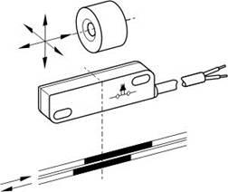
Each Door Open Sensor is made up of two parts. A magnet and a switch. The magnet will be attached to the door. The switch will be attached to the door frame.

Depending on the relative position of magnet and switch, the switch will open or close. With the proper placement, this will allow the detection of the door being opened or closed

Once the switch is wired to an input of the Frotcom GPS/GPRS device; these changes will be detected and communicated to the Frotcom Data Center.

Then, Frotcom will update the door open status for that vehicle and check for alarm conditions.
*


Main features
Here are some of the main features of the Door Open Sensor:
  • Thermoplastic enclosure
  • Flat design
  • Long life
  • Non-contacting principle
  • 1 reed contact
  • Actuating distance up to 60mm
  • Actuating surface marked by protrusion
  • Pre-wired cable with length 1m
  • Protection class IP 67


Thursday, 20 June 2013

BURGLAR ALARM


http://bits.wikimedia.org/static-1.20wmf11/skins/common/images/magnify-clip.png
A burglar alarm is a system designed to detect intrusion – unauthorized entry – into a building or area. They are also called security alarms, security systems, alarm systems, intrusion detection systems, perimeter detection systems, and similar terms.

Burglar alarms are used in residential, commercial, industrial, and military properties for protection against burglary (theft) or property damage, as well as personal protection against intruders. Car alarms likewise protect vehicles and their contents. Prisons also use security systems for control of inmates.

Some alarm systems serve a single purpose of burglary protection; combination systems provide both fire and intrusion protection. Intrusion alarm systems may also be combined with closed circuit television surveillance systems to automatically record the activities of intruders, and may interface to access control systems for electrically locked doors. Systems range from small, self-contained noisemakers, to complicated, multi-area systems with computer monitoring and control.


Sunday, 9 June 2013

GAS SENSOR MQ-6


Whenever there is LPG concentration of 1000 ppm (parts per million) in the area, the OUT pin of the sensor module goes high. This signal drives timer IC 555, which is wired as an a stable multivibrator. The multivibrator basically works as a tone generator.

Output pin 3 of IC 555 is connected to LED1 and speaker-driver transistor SL100 through current-limiting resistors R5 and R4, respectively. LED1 glows and the alarm sound to alert the user of gas leakage. The pitch of the tone can be changed by varying preset VR1. Use a suitable heat-sink for transistor SL100.


Gas Sensor MQ-6

 FEATURES

High sensitivity to LPG, ISO-butane, propane
Small sensitivity to alcohol, smoke.
Fast response.
Stable and long life
Simple drive circuit

APPLICATION

They are used in gas leakage detecting equipments in family and industry, are suitable for detecting of LPG, ISO-butane, propane, LNG, avoid the noise of alcohol and cooking fumes and cigarette smoke.


Tuesday, 4 June 2013

TEMPERATURE SENSOR LM35

General description of  LM 35


The LM35 is an integrated circuit sensor that can be used to measure temperature with an electrical output proportional to the temperature (in oC) The LM35 series are precision integrated-circuit temperature sensors, whose output voltage is linearly proportional to the Celsius (Centigrade) temperature. The LM35 thus has an advantage over linear temperature sensors calibrated in ° Kelvin, as the user is not required to subtract a large constant voltage from its output to obtain convenient Centigrade scaling. The LM35 does not require any external calibration or trimming to provide typical accuracies of ±1⁄4°C at room temperature and ±3⁄4°C over a full −55 to +150°C temperature range. Low cost is assured by trimming and calibration at the wafer level. The LM35’s low output impedance, linear output, and precise inherent calibration make interfacing to readout or control circuitry especially easy. It can be used with single power supplies, or with plus and minus.

                                                           
LM 35 Temperature Sensor 
                                                      
Features
1.      Calibrated directly in ° Celsius (Centigrade)
2.      Linear + 10.0 mV/°C scale factor
3.      0.5°C accuracy guarantee able (at +25°C)
4.      Rated for full −55° to +150°C range
5.      Suitable for remote applications
6.      Low cost due to wafer-level trimming
7.      Operates from 4 to 30 volts
8.      Less than 60 μA current drain
9.      Low self-heating, 0.08°C in still air
10.  Non linearity only ±1⁄4°C typical
11.  Low impedance output, 0.1 W for 1 mA load

 Advantages of LM35  to Measure Temperature?
You can measure temperature more accurately than a using a thermistor.  
The sensor circuitry is sealed and not subject to oxidation, etc.
The LM35 generates a higher output voltage than thermocouples and may not require that the output voltage be amplified.

Working of LM35:
The scale factor is .01V/oC. 

The LM35 does not require any external calibration or trimming and maintains an accuracy of +/-0.4 oC at room temperature and +/- 0.8 oC over a range of 0 oC to +100 oC.

Another important characteristic of the LM35DZ is that it draws only 60 micro amps from its supply and possesses a low self-heating capability. 

The sensor self-heating causes less than 0.1 oC temperature rise in still air. 

It has an output voltage that is proportional to the Celsius temperature. 

Sunday, 24 February 2013

All About Electronics: Advantages of optical fiber communication

All About Electronics: Advantages of optical fiber communication: Let us see the advantages of optical fiber communication over conventional communication system  Enormous bandwidth: the informati...

Advantages of optical fiber communication


Let us see the advantages of optical fiber communication over conventional communication system 

Enormous bandwidth: the information carrying capacity of a transmission system is directly proportional to the carrier frequency of the transmitted signals. The optical carrier frequency is in the range of 10^14Hz while the radio frequency is about 10^6Hz. Thus the optical fibers have enormous transmission bandwidth and high data rate. Using wavelength division multiplexing operation, the data rate or information carrying capacity of optical fibers is enhanced to many orders of magnitude.

Low transmission loss: due to the usage of ultra low loss fibers and the erbium doped silica fibers as optical amplifiers, one can achieve almost loss less transmission. Hence for long distance communication fibers of 0.002dB/km are used. Thus the repeater spacing is more than 100km. 

Immunity to cross talk: since optical fibers are dielectric wave guides, they are free from any electromagnetic interference (EMI) and radio frequency interference (RFI). Since optical interference among different fibers is not possible, cross talk is negligible even many fibers are cabled together. 

Electrical isolation: optical fibers are made from silica which is an electrical insulator. Therefore they do not pick up any electromagnetic wave of any high current lightening. It is also suitable in explosive environment.

Small size and weight: the size of the fiber ranges from 10 micrometers to 50 micrometers which is very small. The space occupied by the fiber cable is negligibly small compared to conventional electrical cables. Optical fibers are light in weight. These advantages make them to use in aircrafts and satellites more effectively.

Signal security: the transmitted signal through the fiver does not radiate. Unlike in copper cables, a transmitted signal cannot be drawn from a fiber without tampering it. Thus, the optical fiber communication provides 100% signal security. 

Ruggedness and flexibility: the fiber cable can be easily bent or twisted without damaging it. Further the fiber cables are superior than the copper cables in terms of handling. Installation, storage, transportation, maintenance, strength and durability.

Low cost and availability: since the fibers are made of silica which is available in abundance. Hence, there is no shortage of material and optical fibers offer the potential for low cost communication.

Reliability: the optical fibers are made from silicon glass which does not undergo any chemical reaction or corrosion. Its quality is not affected by external radiation. Further due to its negligible attenuation and dispersion, optical fiber communication has high reliability. All the above factors also tend to reduce the expenditure on its maintenance.

Monday, 18 February 2013

Basic structure of optic fiber cable


Basic structure of optic fiber cable
                                               

An optical fiber can be called as a dielectric waveguide. This waveguide operates at optical frequencies.
The fiber consists of three parts namely
1.       Core
2.       Cladding and
3.       Buffer coating

The core of the fiber is cylindrical and has a radius a. its refractive index is represented by n1.

The core is surrounded by a solid dielectric cladding whose refractive index is n2. The refractive index of the core n1 is always greater than the refractive index of cladding n2. The cladding gives mechanical strength to the inner core.

The buffer coating gives additional strength and prevents any damage to the fiber.

Since the cladding that surrounds the core has lower refractive index than the core, the light is guided through the core due to total internal reflection.